Ton Peijnenburg, Fellow TU/e HTSC and manager systems engineering at VDL ETG (FEBRUARY 2019)
A picture is worth a thousand words
In 2017, a series of articles were published on Systems Engineering and HTSC. The first article explained the need for Systems Engineering and the second focused on the importance of multi-disciplinary research and development. The third concerned the role of requirements management in the Systems Engineering process. This fourth entry deals with the engineering benefits of rich pictures.
"A system architect has the task of finding a best fit solution to a set of requirements, starting with the purpose of the system and taking into account its context"
RICH PICTURES TO SEE THE BIG PICTURE
Pictures are a powerful means to convey information: after all, “a picture is worth a thousand words.” A system architect has the task of finding a best fit solution to a set of requirements, starting with the purpose of the system and taking into account its context. Small systems may be handled by a single designer; when it comes to more elaborate systems, a team of designers typically shares responsibility for developing a solution.
In the single-person case, pictures may help to structure one’s thoughts and maintain an administration of a system under development. For structuring one’s thoughts, one can think of a mind map – a diagram to visually organize information. Mind maps are oftentimes used to organize information from a brainstorming session, offering hierarchical organization around a central theme. Another commonly-used tool is a block diagram. Blocks represent functions or modules and are connected by lines that show relationships or information flows. Pictures such as mind maps and block diagrams evolve over time and may be hierarchical in order to capture more detailed aspects of a system as development progresses.
In the case of design teams with multiple people, diagrams offer the additional benefit of synchronizing individual ideas about the system that is being developed. A structure can be formulated and explained most easily when the relationships between elements are indicated, highlighted and emphasized. The shared visual view will help team members to remain synchronized on the system’s scope, elements, connections, etc. Again, the diagrams are not static but evolve over time. Ideally, incremental adaptations to the diagrams will be made when the team is present so that everyone will be on the same page regarding the underlying reasoning. In other cases, visual elements in the diagrams will help to reconstruct the reasoning and logic.
CHARTING THE PROGRESS
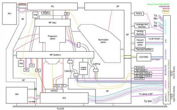
At Philips Center for Industrial Technology, we spent a reasonable amount of time developing layered block diagrams in which the blocks represent physical modules and the connecting lines indicate interactions. The lines have colors that indicate the type of interaction: mechanical (force, displacement, structural and acoustic vibrations), heat, contamination, etc. These block diagrams are called Interface Discussion Drawings. They were created with the purpose of a) communicating information about interfaces, b) laying down design rationale and c) transferring design knowledge. See Figure 1 for an example of such a drawing.
During the training of mechatronic system designers on the PDEng program at TU/e, emphasis is placed on such sketches and drawings. In the final assignment of the trainees, a system design task is executed for an industrial partner over the course of one year. Trainees are encouraged to already start making drawings of their system when first discussing their assignment. The schematic drawings will grow more complete over time, with elements of knowledge and design being added. In the progress presentations, these drawings should be shown, preferably early on, to create a reference point for the audience. This is the ideal situation and is not always achieved in practice. However, sketching and drawing do not appear to be trivial skills for engineers anymore.
THE ENGINEER OF 2020
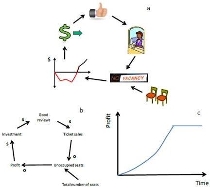
While reading about system thinking and how to train engineers in this, I came across an article from Iowa State University that discussed how to train the engineer of 2020. System thinking skills are a key asset of the new engineer, and are tied to three fundamental tools for system thinking: rich pictures, causal loop diagrams and behavior-over-time graphs. These graphical tools (see Figure 2) capture key elements of systems, documenting their elements, connections and behavior in an abstract manner. In a sense, the Interface Discussion Drawings can be considered rich pictures with a domain-specific graphical language. Like rich pictures, they document essential elements of a system in a very insightful manner. Individuals and teams can use these in their development projects.
A LIFELONG SKILL
In addition to the pictures discussed, there are many more visual and graphical representations that can be made of systems. Given that children already start using mind maps at elementary school, I believe that it is critical for future engineers to build on these skills. Engineers should develop a reflex to make sketches and drawings when discussing their design work; they will thus be more efficient and effective in their work. If you’re interested, there is a lot to be read about rich pictures and their relatives, but if I were you, I would start sketching right away – the sketches and drawings will be improved by the discussions about them, not by the theory behind them!