DISCRETE ROBOTIC ASSEMBLIES
Robotics in the built environment include the use of digital technologies to design, produce, and assemble products related to the built environment, often resulting in structures. This includes the use of computer- aided design (CAD) software, 3D printing, and other advanced manufacturing technologies that allow for greater precision, efficiency, and customization in the building process.
In the built environment, computational design can be used to create custom building components, such as prefabricated walls or structural elements, which can be easily assembled on site. It can also be used to produce customized building facades or interiors, allowing for greater architectural creativity and flexibility.
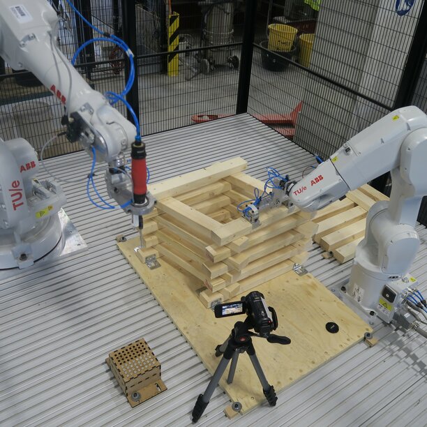
ROBOTIC ASSEMBLY OF A TIMBER TOWER
Laura Vrenken
As part of her graduation project, Laura Vrenken has designed a parametric column with an optimized shape that minimizes the most critical internal force, which is the tension in the screw connections between the beams. This optimization involves smoothing the wind surface area and balancing the tensile forces for each wind direction. As a result, the maximum tension force has been reduced by 43% compared to a straight column.
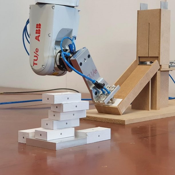
The parametric column will be robotically constructed by two robotic arms that work together. One of the robots will pick up a timber beam and place it in the correct location using a pneumatic gripper. The other robot will then pick up a screw and fasten it into the timber beam. By ensuring that the robots wait for each other before proceeding with the next step and by carefully planning their paths, the entire structure can be built without any collisions.
The final outcome of the project is a full-sized timber column that has been both robotically constructed and structurally optimized. Moreover, the project has resulted in the development of a robotic setup that can automatically assemble a timber structure using screws.
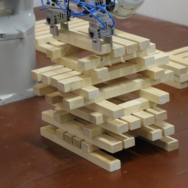
PARAMETRICALLY DESIGNED TOWER
Robin van Steen and Saar Driessen
For the "Digital Design and Manufacturing" course, the assignment was to create a structural element (such as a wall or column) using two different types of beam elements, one shorter and one longer. The parametric model and robot code was created using Grasshopper.
The concept for this project was to build a tower, with each layer being based on the layer below it. For instance, the beams might move inward or outward relative to the beam below for a few layers and then change direction again. The number of layers before the direction switches from inward to outward (or vice versa) is an input variable. The first two layers were determined as input variables.
There were three important decisions to be made for each layer: the position of the beams, the type of beam, and the number of beams. These were all based on the layer below and the number of layers between direction changes. The specific rules were formulated with structural principles in mind.
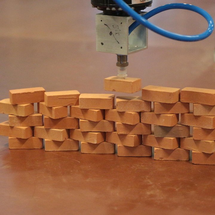
A framework on how to cope with geometric uncertainties of robotic manufacturing processes of brick structures
Amy Hendriks
In order to expand the use of robots in the built environment, research is needed on methods for addressing potential vulnerabilities that may arise during the manufacturing process, such as vibrations, wind, material imperfections, or fabrication inaccuracies.
These vulnerabilities can result in differences between the original digital design and the physical model constructed by the robot. A framework has been established in which a digital design is created that can be constructed by the robot. During the construction process, the physical structure is measured and this data is used to create a digital twin of the structure. A structural analysis is then performed to determine any differences between the physical structure and the original digital design and the implications of these differences. This analysis allows for the determination of whether the structure can be safely continued or if adjustments to the design must be made to prevent collapses. By acknowledging the potential geometric vulnerabilities of robotic manufacturing processes, analyzing during construction, and adjusting the design as needed, it is hoped that robotic manufacturing processes will be able to be more widely applied in the built environment.
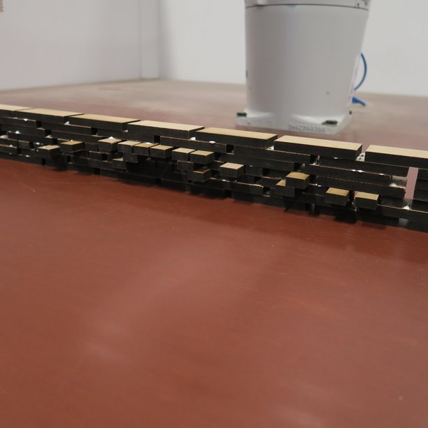
Morse Code Wall
Laura Dings, Sebastiaan van Hassel and Tom Diks
For the "Digital Design and Manufacturing" course, the assignment was to create a structural element (such as a wall or column) using four different types of bricks. here were two line-like bricks, a shorter one and a longer one, which led to the connection being made with Morse code (short dots and long stripes). This inspired the idea to create a script in which the user could input a sentence, and a robot could turn it into a wall using Morse code, with each layer representing a word. Since not all words had the same length in Morse code, there could be floating bricks. To address this issue, the additional two brick types were used to fill the remaining space at the edges. One of the main challenges was ensuring the stability of the wall, which was complicated by the open spaces between each letter that could result in floating or unstable bricks. The script was therefore expanded with a thorough stability check that also took the stacking sequence into account.